Af Konstruktionsingeniør Kristian Flyvholm IABSE Conference - Creativity and Collaboration, Bath United Kingdom, April 19-20, 2017
Kristian Flyvholm
Søren Jensen A/S, Aarhus, Denmark
Contact: krf@sj.dk
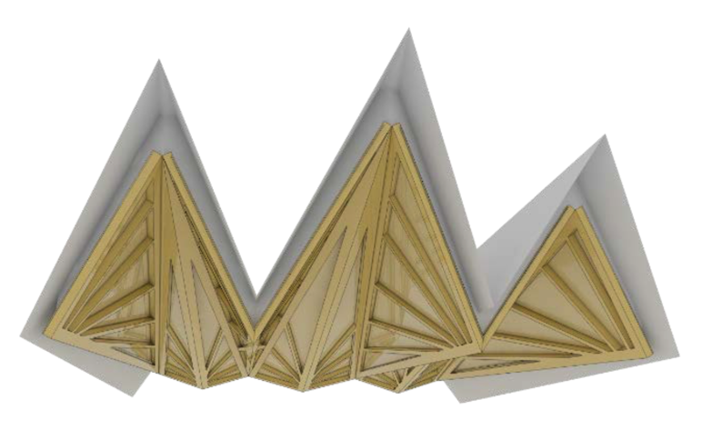
ABSTRACT: This paper describes the design process of a complex roof structure hovering above a relaxing spa and wellness center. The roof structure is a special structure inspired by folding a piece of paper – not into long rectangular planes, but instead into triangular planes. Visually the roof structure is split into two layers which sit, on top of each other. The bottom layer is the primary load carrying structure made of laminated timber frames, and the top layer is a cladding layer with wooden tiles on timber purlins that extends beyond the bottom layer. Within each triangular frame is a fan of laminated timber members that grow out from the point where the frame is supported by a column.
KEYWORDS: complex geometry, folding plates; timber frame; Rhino/grasshopper; computational design; parametric design flow, virtual reality.

Figure 1 Illustration of the folding roof structure
1. INTRODUCTION
The overall architectural concept was to create a unique roof structure reflecting the surrounding terrain. The terrain to the west is somewhat hilly whereas the terrain to the east is mostly flat. The roof structure reflects the terrain with tall marked rises varying from 6 to 10m towards west and less marked rises toward east.
Three materials dominate the project: Natural stone, glass and timber. This paper is focusing on the roof structure which is all done in timber. Visually the roof structure appears to float over the massive stone walls, with a minimum of slender support columns.
The distinct eaves of the building to the west are scaled proportionally to match the taller rises of the roof structure, which creates a coherent appearance. The eaves have a secondary function as shading which is necessary with the a very tall glass façade.
2. THE ART OF COMMUNICATION
This paper describes the design process of the complex roof structure hovering above the massive stone walls at the relaxing spa- and wellness center. In a design phase, you have to make a lot of decisions, but in the early stage you don’t always have enough knowledge to make the right decision. A proper parametric design workflow could help to gain vital knowledge by making a lot of superfast iterations at the early stages. Consequences as a result of change in the design are shown almost real time, and there is no delay in answering your client.

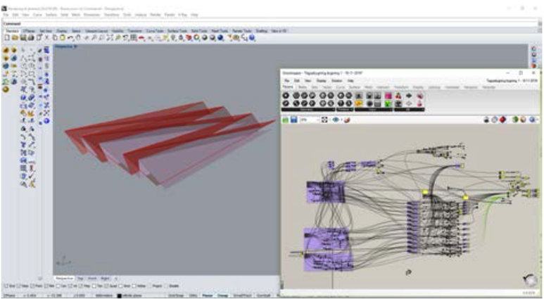
Figure 2 Rhino/Grasshopper model
2.1 Workflow
As a part of the early design a number of “rules” were applied. These “rules” were transformed to a script in a parametric environment using Rhino and Grasshopper. In this environment the complex geometry of the roof structure was created. This made it possible to make real time changes to the geometry with just a change of simple number slider.
2.1.1 Rhino/Grasshopper
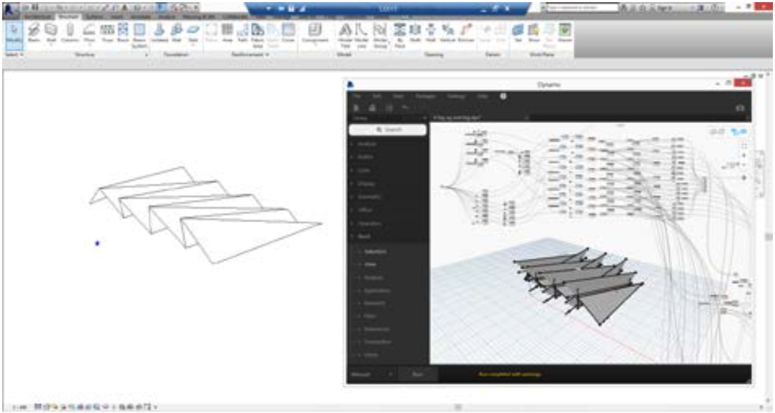
In the same script, several analyses were done which made it easy to review consequences in statics, materials, shading, indoor climate etc. The parametric model made it easy to create an endless number of variations to the design. A selected range of design variations were pinned out and some were printed into physical models. In addition to the physical models, the form finding process took place in a Rhino /Grasshopper /Karamba /ladybug (parametric design tools) environment, and were transformed into a Revit model. As a part of the workflow it was essential to ensure a fast interoperability between parametric design tools used in the Rhino/grasshopper environment and the Revit platform. In this case, we used a script in dynamo (plug in for Revit) to convert models generated in the early stage/concept phase into the more common Revit workflow.
2.1.2 Collaboration in Revit
Architects, Engineers and contractors were, in this case, collaborating within the Revit universe. This is a known platform for engineers, architects and contractors and a normal environment in terms of communication. But it is also a technical environment, and you must have a certain knowledge within the area of building information module (BIM) to understand the models and output (blueprint, technical drawings, 3D-models).

Figure 3 Interoperability between Rhino/Grasshopper and Revit/Dynamo
2.2 Communication with the builder
The collaboration between all the design contributors where ensured, but there was still a very vital missing link. The way communication with the builder was dealt with. It is most likely that the one who is ordering the building, is the one with the least experience in reading and understanding complex building drawings. That’s why communication at this level is extremely important. In this case a chosen number of design options was converted to a Virtual Reality environment. The builder then had a perfect basis to comment on the design as he literally was walking around in the building he was about to start building. And with the parametric model already generated, the process of changing and analyzing the design was easy to implement. Within very few steps another Virtual Reality scene could be generated.
3. DISCUSSION AND CONCLUSION
This case was used to try out a new workflow and especially the last output generated as a virtual reality scene has a lot of potential. The feedback we have gotten on both the parametric modelling workflow and the communication via virtual reality has simple been great.
This is surely an area that we look forward to develop further in our next cases.

